Valve
 Chemical Reactor Design Toolbox Reference Manual
Chemical Reactor Design Toolbox Reference Manual ChemReactorDesign.Basic.Gas.Transport.Valve

Description
The component generates a volumetric flow rate due to a pressure difference between the ports for a control valve (Sigurd Skogestad, 2009). To allow for a change in sign upon reversal of flow direction and to eliminate singularities due to flow reversal a modified relation is used
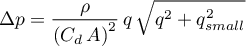
with  as the relative capacity coefficient with is related
to the value oflost velocity heights
as the relative capacity coefficient with is related
to the value oflost velocity heights

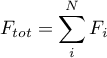
Then the molar flow rates become
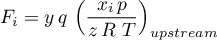
with 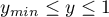 as control signal to externally adjust
the calculated volumetric flow rate.
as control signal to externally adjust
the calculated volumetric flow rate.
The energy flow rate is determined as
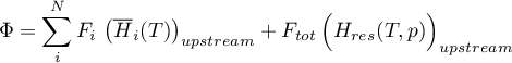
with
The positive flow direction is from port A to port B.
Assumptions and Limitations
The parameter  is internally set to a value of
  .
.
Ports
Conserving
Gas conserving port
Port_A = Gas; %
Gas conserving port
Port_B = Gas; %
Input
Physical control signal
yin = {0,'1'};The signal
is used to control the calculated
volumetric flow rate.
Physical signal that represents the cross sectional area
Ain = {0,'m^2'};Dependencies: The port is only visible when
areaInputis set toOn.
Output
Physical signal that represents the volumetric flow rate at upstream conditions
qout = {1,'l/s'};Dependencies: The port is only visible when
flowOutputis set toOn.
Parameters
Options
Option to select area input
areaInput = OnOff.Off;
On|OffOption to select flow output
flowOutput = OnOff.Off;
On|OffOption to set check valve
checkValve = OnOff.Off;
On|Off
Geometry
Cross sectional area
A0 = {0,'m^2'};Dependencies: The parameter is only visible when
areaInputis set toOff.
Mass Transport
Number of lost velocity heights
n = {1,'1'};Minimum Control Signal
ymin = {1.0e-06,'1'}; % Minimum Control Signal
Nomenclature
 |
molar flow rate of species Ai |
 |
molar enthalpy of species Ai |
 |
departure enthalpy of the mixture |
 |
total number of species |
 |
pressure |
 |
volumetric flow rate |
 |
time |
 |
temperature |
 |
mole fraction of species Ai |
 |
compressibility |
 |
control signal |
 |
control signal |
 |
energy flow rate |
Bibliography
Sigurd Skogestad (2009). Chemical and Energy Process Engineering, CRC Press.